
Enviroflex GmbH is an Austrian engineering company that designs, manufactures and supplies high-quality machinery and systems as well as implementing plants and executing turnkey projects in three main fields:
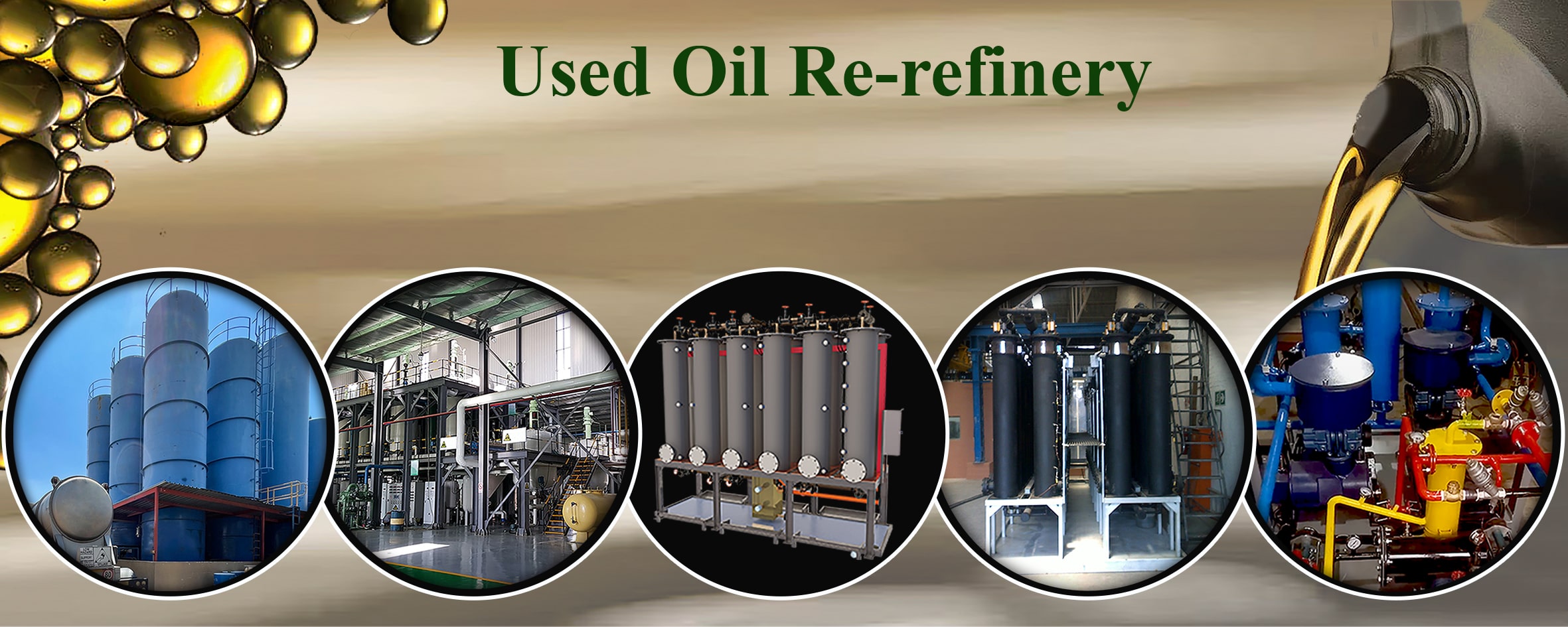
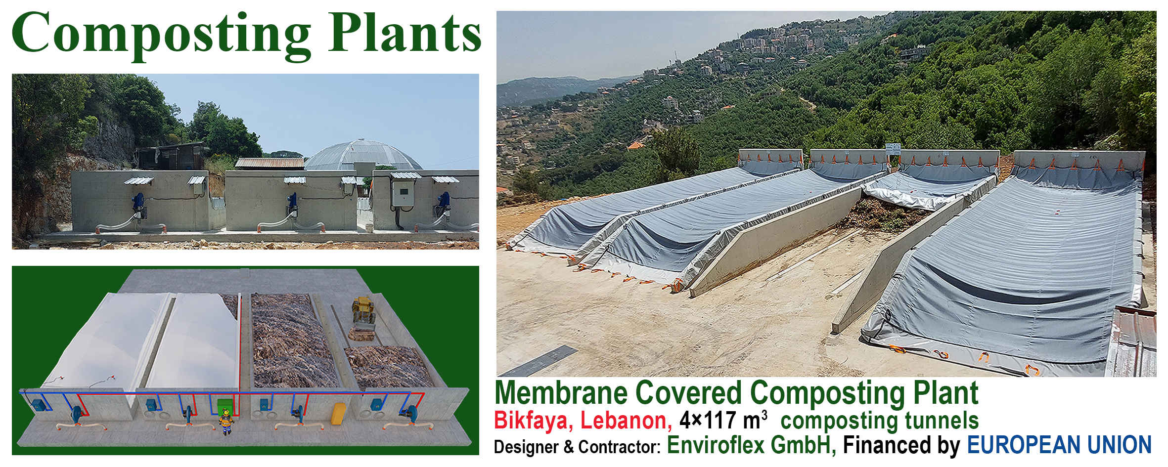
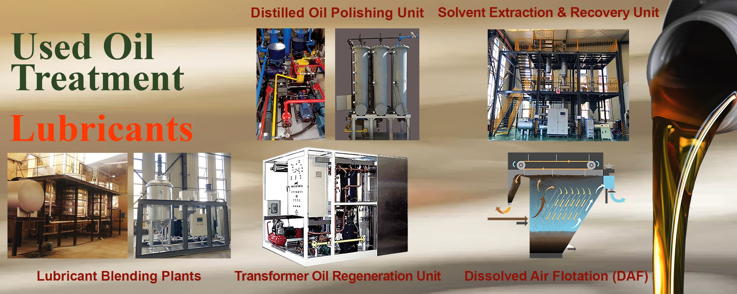
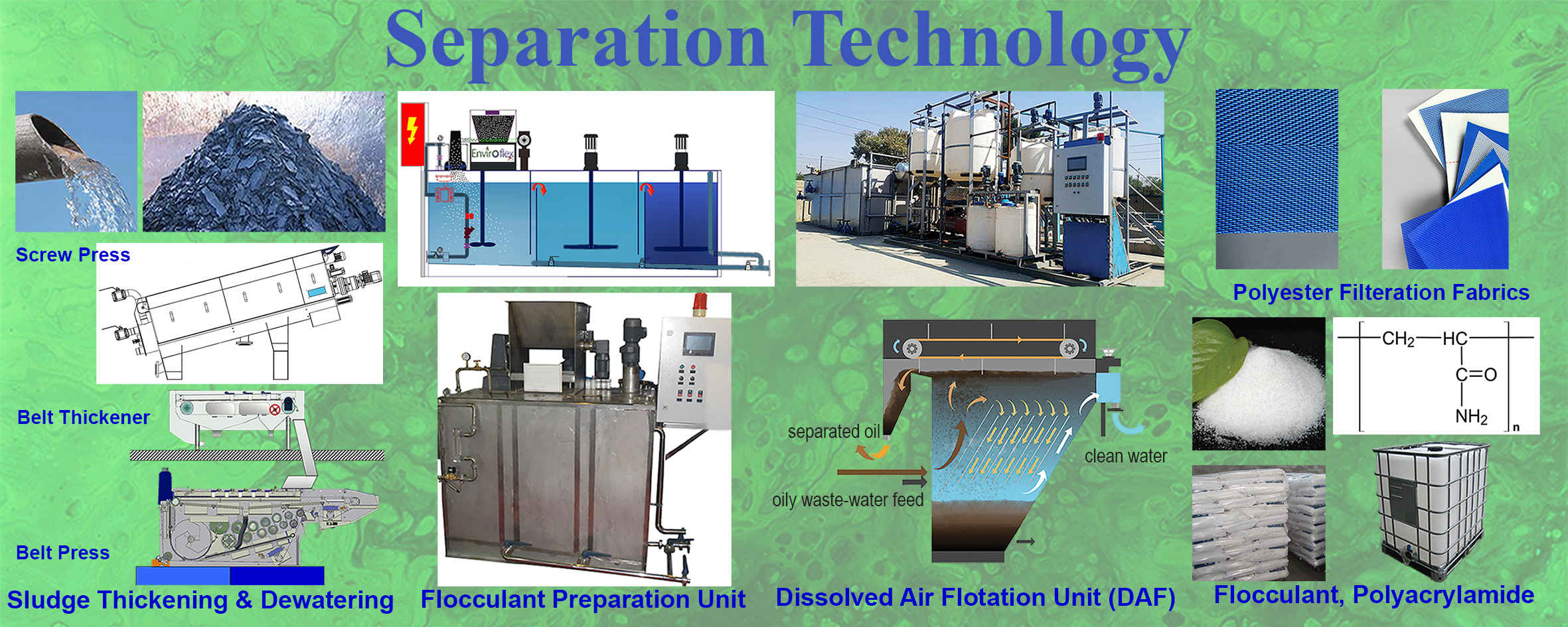
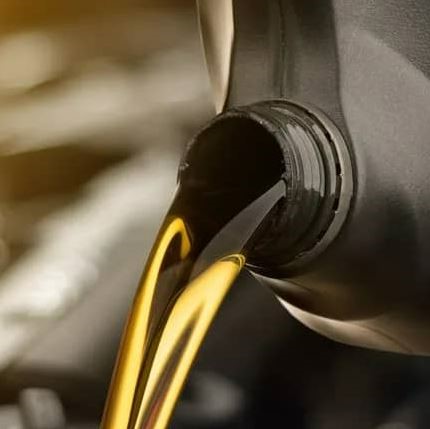
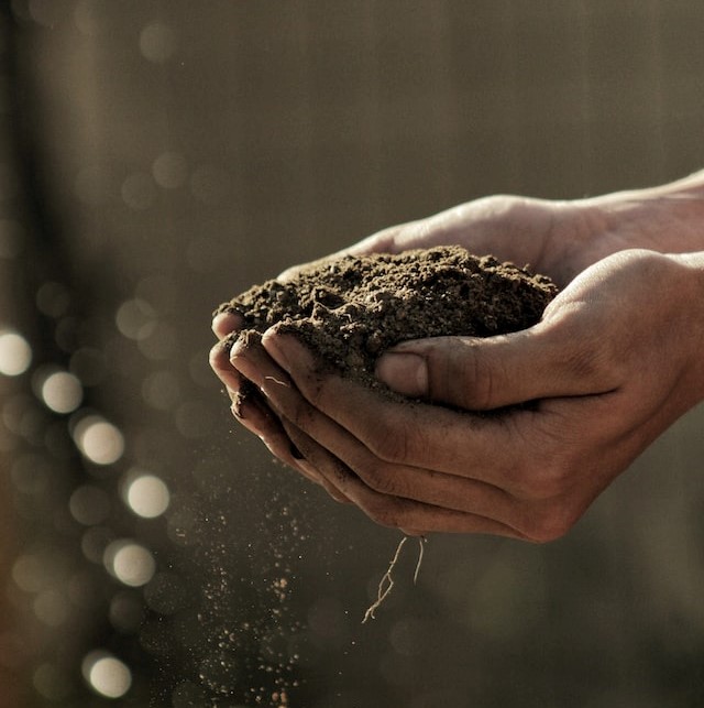
Used Lube Oil Treatment and Lubricants | Membrane Covered Composting Plant | Separation Technology
With different applications in Used Engine Oil Re-refineries as well as Water and Waste-Water Treatment projects and Composting Plants. Enviroflex GmbH also manufactures Oil Polishing Unit with Bauxite Sorbent including Sorbent Reactivation. Enviroflex GmbH also delivers Membrane Cover Composting Plants, Quality Membranes, Flocculant Preparation units, Sludge Thickening & Dewatering projects, Flocculant, and Filtration Fabrics.
| Cookie | Dauer | Beschreibung |
|---|---|---|
| cookielawinfo-checkbox-analytics | 11 months | This cookie is set by GDPR Cookie Consent plugin. The cookie is used to store the user consent for the cookies in the category "Analytics". |
| cookielawinfo-checkbox-functional | 11 months | The cookie is set by GDPR cookie consent to record the user consent for the cookies in the category "Functional". |
| cookielawinfo-checkbox-necessary | 11 months | This cookie is set by GDPR Cookie Consent plugin. The cookies is used to store the user consent for the cookies in the category "Necessary". |
| cookielawinfo-checkbox-others | 11 months | This cookie is set by GDPR Cookie Consent plugin. The cookie is used to store the user consent for the cookies in the category "Other. |
| cookielawinfo-checkbox-performance | 11 months | This cookie is set by GDPR Cookie Consent plugin. The cookie is used to store the user consent for the cookies in the category "Performance". |
| viewed_cookie_policy | 11 months | The cookie is set by the GDPR Cookie Consent plugin and is used to store whether or not user has consented to the use of cookies. It does not store any personal data. |